


This tutorial uses the control panel of the Cyber6-key toggle multi-switch as a case install guide
Table of Contents
- Preface: Working Principle and Prerequisites
- Step 1: Step 1: Locate and Cut the Two Wires in the X Series 4-inch Harness That Connect to the Off-Road Lights
- Step 2: Understand the Functions of the Different Colored Wires in the X Series 4-inch Harness
- Step 3: Connect the Four Wires to the Ports on the Control Panel
- Step 4: Connect the Harness to the Off-Road Light Harness Ports
- Step 5: Secure the Off-Road Lights to Your Vehicle
- Step 6: Test if the Lighting Functions Normally
- Summary
Preface: Working Principle and Prerequisites
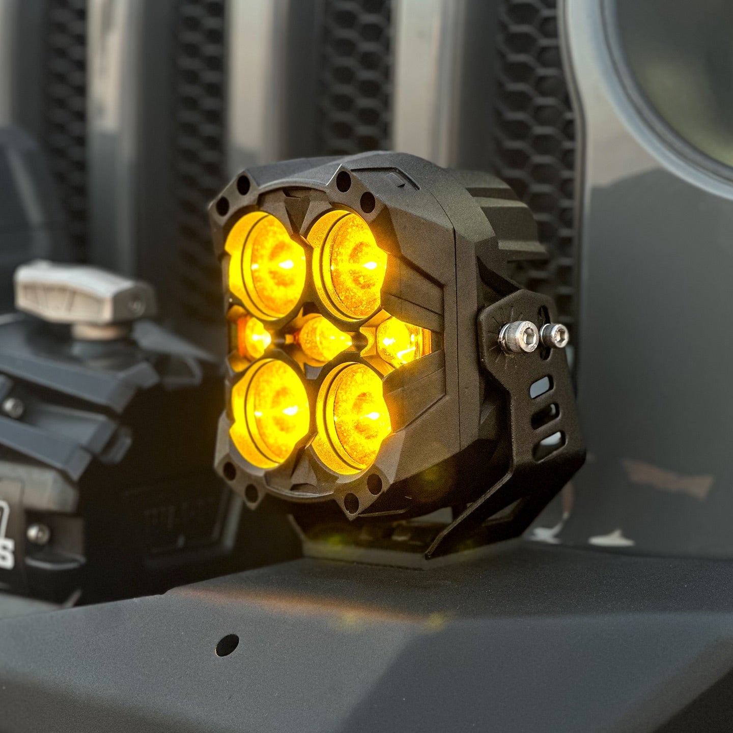
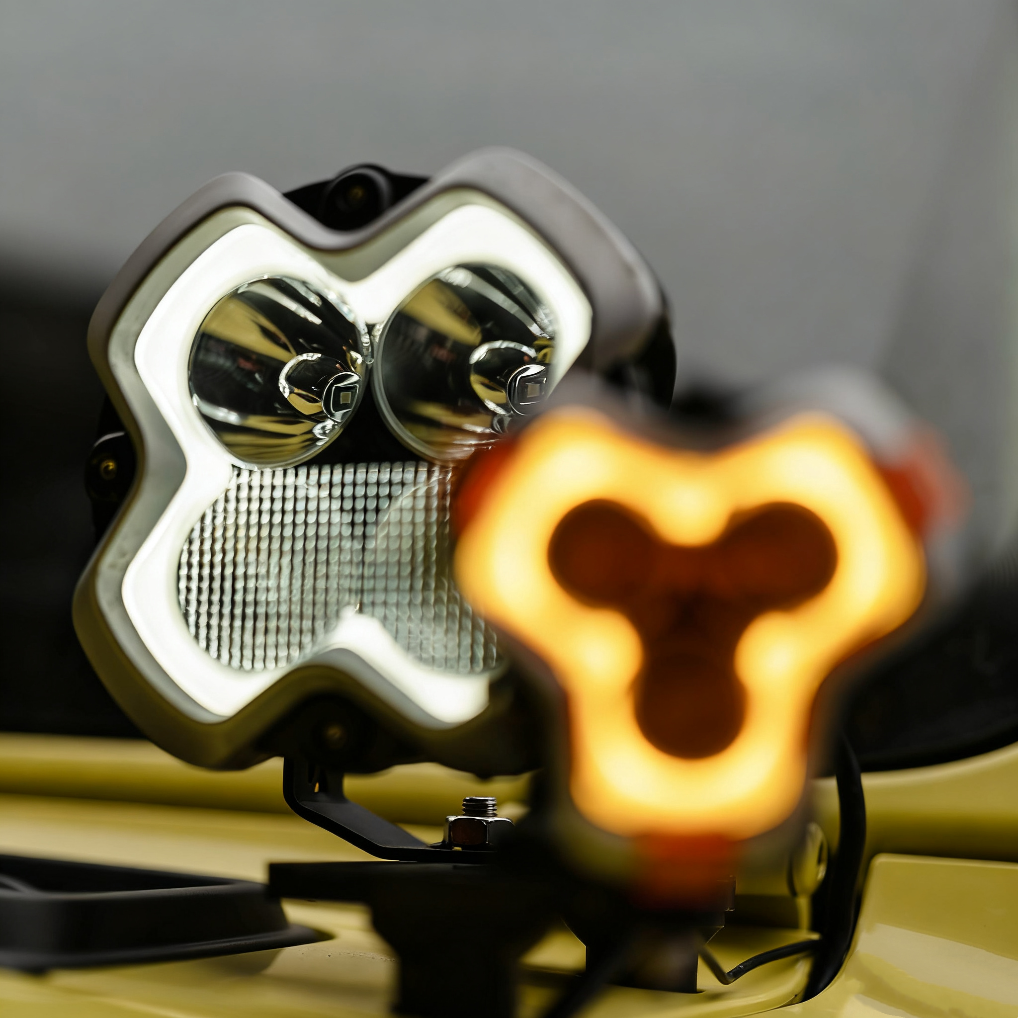
The X Series 4-inch off-road spotlights come with red and white daytime running light (DRL) functions, which can be controlled via the original controller switch. Therefore, some users attempt to connect the black and red wires from the original X Series 4-inch wiring harness to the multi-switch panel instead of using the original harness's control switch to operate the DRLs. So, if you want to directly use the control panel to manage the different lighting modes of the X Series 4-inch off-road lights, you need to cut the X Series 4-inch wires, extract four wires from the harness, and then connect these four function-specific wires to the multi-switch control panel. This allows each button to correspond to a specific lighting function.
Working Principle
By directly connecting four different X Series 4-inch wires to different ports on the switch panel, the buttons on the control panel can directly control the various lighting effects of the X Series 4-inch lights.
Note: If you intend to connect the X Series 4-inch lights to the control panel, you must disconnect the original wires. For each stripped wire harness (one harness contains 4 thin wires, so two harnesses have a total of 8 thin wires), connect the corresponding stripped wires to the ports on the control panel.
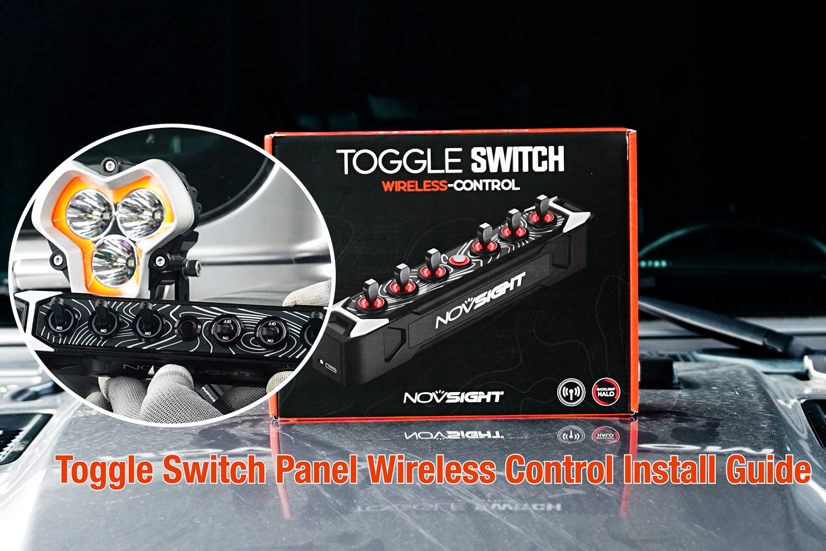
Prerequisites
A prerequisite for this X Series 4-inch wire-splicing installation is that you first disconnect the car's power supply and connect the multi-switch control panel to the car's battery.
If you have not yet installed the switch control panel in your vehicle, refer to the following tutorial videos:
Novsight Bluetooth Control Panel Installation Tutorial: https://www.youtube.com/watch?v=V8kqZtToU5o
Novsight HALO Series Voice-Controlled Switch Panel Installation Tutorial: https://www.youtube.com/watch?v=2SIlYlM9Pfg
Step 1: Locate and Cut the Two Wires in the X Series 4-inch Harness That Connect to the Off-Road Lights
Schematic diagram of the X Series 4-inch wiring harness is as follows:

Cut the wires at the two ports that connect to the off-road lights, leaving only two wires attached to each port:


You will see that each harness contains four wires of different colors: red, black, white, and yellow.

Discard the remaining part of the harness that includes the controller and fuse, as these components will no longer be functional after cutting the harness.


Step 2: Understand the Functions of the Different Colored Wires in the X Series 4-inch Harness
The four different colored wires of the X Series 4-inch lights correspond to specific functions:
- The black wire is the negative connection wire, and the red wire is the positive connection wire, which controls the white main light source.
- The white wire is the switch connection wire for controlling the white daytime running lights.
- The yellow wire is the switch connection wire for controlling the yellow daytime running lights.
Step 3: Connect the Four Wires to the Ports on the Control Panel

Connect the X Series 4-inch wires to the control panel as follows:

- The red wire toggles the main light on and off. The red wire and black wire must be connected to the same channel: the red wire to the positive terminal, and the black wire to the negative terminal.
- The white wire (for white DRL control) connects to the same channel; only the positive terminal needs to be connected, and the negative terminal is not required.
- The yellow wire (for yellow DRL control) connects to the same channel; only the positive terminal needs to be connected, and the negative terminal is not required.
Note: Connect wires of the same color to the positive terminals of the multi-switch
Each set of lights has corresponding wires. For example:
- If there are two sets of lights, there will be 4 white wires, 4 yellow wires, 4 red wires, and 4 black wires.
- If there are four sets of lights, there will be 8 white wires, 8 yellow wires, 8 red wires, and 8 black wires.
- Be careful not to connect wires of different colors to the same multi-switch terminal.
Step 4: Connect the Harness to the Off-Road Light Harness Ports
Each off-road light comes with its own harness. Simply connect the four ports at the end of the harness one by one:


The end of the harness has four color-coded interfaces. Connect wires of the same color together:
- Red to red
- Black to black
- White to white
- Yellow to yellow

Step 5: Secure the Off-Road Lights to Your Vehicle

You can adjust the order of this step as needed; you may also choose to secure the off-road lights to your vehicle first.
Step 6: Test if the Lighting Functions Normally
After completing Steps 1 and 5, turn on the car's power, start the vehicle, and check if the functions of the control panel and the corresponding X Series 4-inch off-road lights work properly.
Let's review the functions of the different X Series 4-inch wires again:

- Black: Negative connection wire; Red: Positive connection wire (controls the white main light source)
- White: Switch connection wire for white daytime running lights
- Yellow: Switch connection wire for yellow daytime running lights
Test the different lighting effects as follows:
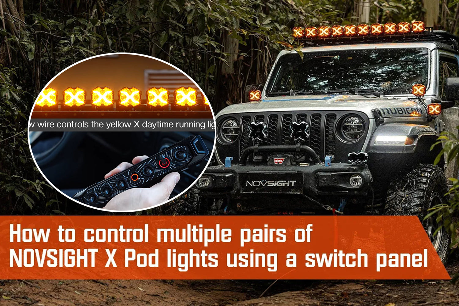
- The button connected to the white wire controls the white DRLs. Flip the toggle switch for the corresponding channel to turn them on.
If the corresponding channel on the controller is activated, a red circle will be displayed on the controller (this is only a demonstration of the lighting effect, not a real-time image).

- The button connected to the yellow wire controls the yellow DRLs. Flip the toggle switch for the corresponding channel to turn them on.
If the corresponding channel on the controller is activated, a red circle will be displayed on the controller (this is only a demonstration of the lighting effect, not a real-time image).

- The button connected to the red wire controls the white main light source in the middle of the off-road lights. Flip the toggle switch for the corresponding channel to turn it on.
If the corresponding channel on the controller is activated, a red circle will be displayed on the controller (this is only a demonstration of the lighting effect, not a real-time image).

- When the off-road light is covered with an amber cover, that light will shows yellow
When the off-road light is covered with an amber cover even though the original color of the main light source is white, the light will appear yellow after passing through the amber cover (this is only a demonstration of the lighting effect, not a real-time image).

Summary
Although the X Series 4-inch wire-splicing installation to the control panel involves multiple steps, it is not complicated. The main challenge is to remember the functions corresponding to the different colored wires and correctly connect the wires to the appropriate ports on the control panel.
Except for the red and black wires, which need to be connected to the same port, all yellow wires of the same color should be connected to one port, and all white wires of the same color to another port. This principle applies even when installing multiple sets of lights.
For the same color (e.g., white), whether connecting two or four wires, they should all be connected to the same port.
Therefore, be careful not to connect wires of different colors to the same multi-switch terminal, as this will cause the harness to malfunction.
Relevant Installation Video Links:
- HALO Pro Hardwired Installation to Bluetooth Switch Panel: https://www.youtube.com/watch?v=OamqPAzaIyE
- HALO Pro Series connect to Voice-Controlled Switch Panel:https://www.youtube.com/watch?v=2SIlYlM9Pfg
- HALO SE Connect to Switch Control Panel:https://www.youtube.com/watch?v=hGGAjQRVRGE
- Cyber 6-inch Use Switch Panel Kit Connection Tutorial:https://www.youtube.com/watch?v=nFfv9Go9mSs
- For Multiple HALO Versions connect to Voice-Controlled Switch Panel:https://www.youtube.com/watch?v=XigJtwcFxuI
Purchase Links
Shop X Series LED Pod Lights: https://www.novsights.com/collections/x-series-led-pod-light
Shop Novsight Switch Panels: https://www.novsights.com/collections/switch-panel
Dejar un comentario
Todos los comentarios se revisan antes de su publicación.
Este sitio está protegido por hCaptcha y se aplican la Política de privacidad de hCaptcha y los Términos del servicio.