


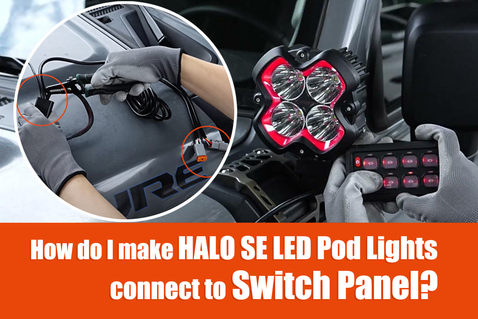
How do I make HALO Pro LED Pod Lights connect to Voice-Controlled Switch Panel?
This tutorial only applies to HALO Pro Series 3-inch, 4.5-inch, and 6-inch LED Pod lights. HALO Pro series 8-inch LED Pod Lights and 20-inch LED light bars are not suitable
Table of Contents
- Preface: Working Principle & Prerequisites
- Step 1: Locate and Cut the HALO Pro Wires Connected to the Off-Road Lights
- Step 2: Understand the Function of Each HALO Pro Wire Color
- Step 3: Connect the Wires to the Switch Panel Ports
- Step 4: Connect the Wiring Segments to the Off-Road Light Harness
- Step 5: Mount the Off-Road Lights on the Vehicle
- Step 6: Test the Lighting Functions
- Summary
Preface: Working Principle & Prerequisites
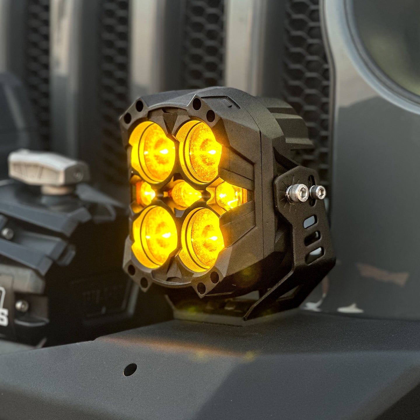
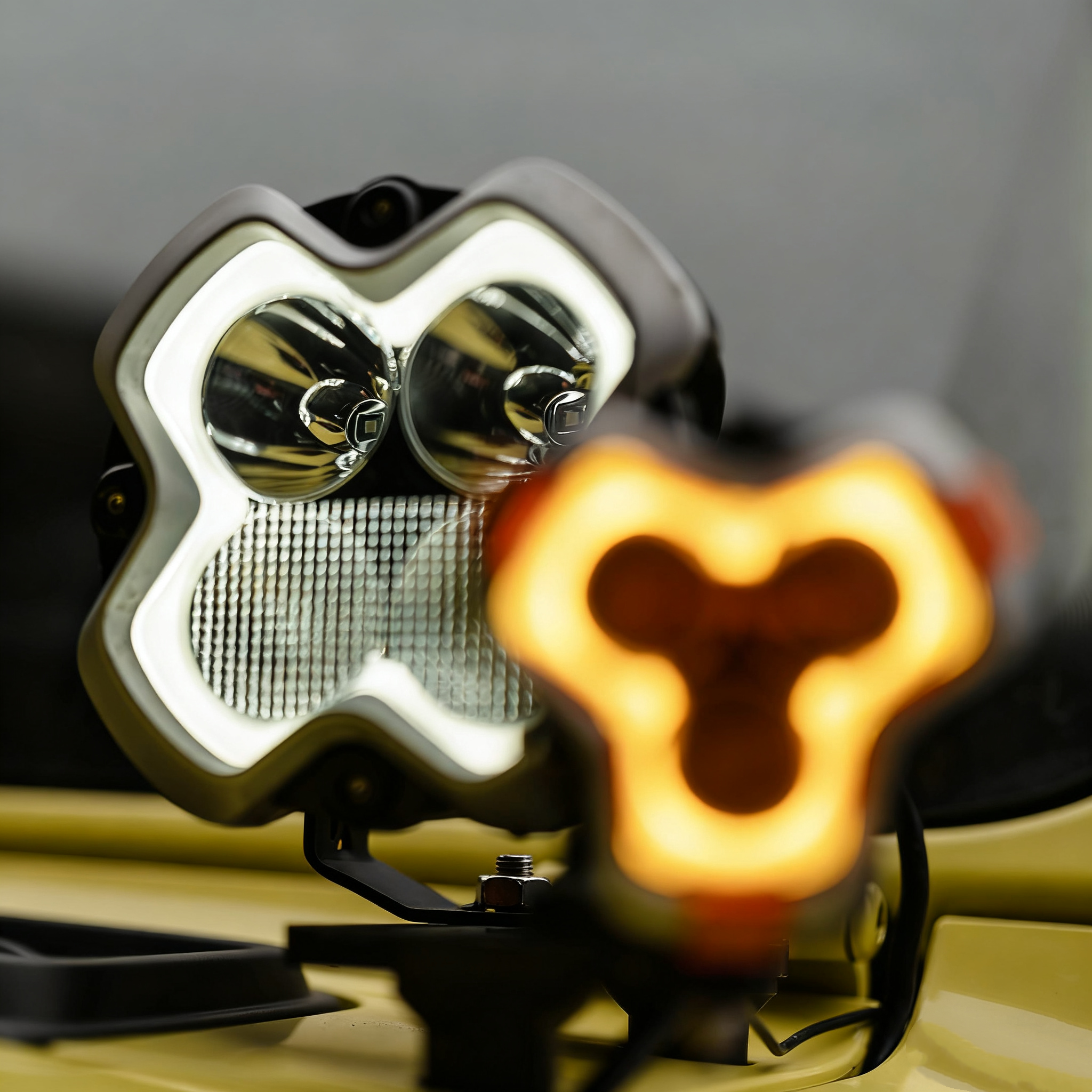
The HALO Pro series off-road spotlights feature dynamic daytime running lights (DRLs) and dual-color temperature lighting. Some users have attempted to connect the original HALO Pro wires (black, red, and white ACC wires) directly to a multi-switch control panel, only to find that the dynamic DRLs either fail to function properly or require extensive operations via HALO’s original built-in controller to work normally.
However, if you cut the HALO Pro wiring harness, strip out four wires from each main harness, and connect these four function-specific wires to the multi-switch control panel, you can achieve one-to-one control (each button controlling a specific lighting function). This guide is demonstrated with the HALO Series Voice-Activated 8-Button Multi-Switch.
Working Principle
By directly connecting four different HALO Pro wires to separate ports on the control panel, each button on the panel can independently control a specific lighting function of the HALO Pro.
Note: To connect the HALO Pro to the control panel, you must first disconnect the original wiring. After stripping the insulation from the corresponding wires, you will obtain four color-coded function wires from each main harness (8 wires total, grouped into two sets of 4). These wires will then be connected to the ports of the control panel.
Prerequisites
Before starting this hardwired installation for the HALO Pro, you must: Disconnect the vehicle’s power supply. Connect the multi-switch control panel to the vehicle’s battery first.
If you have not yet installed the switch control panel in your vehicle, refer to the following tutorial videos:
Novsight Bluetooth Control Panel Installation Tutorial: https://www.youtube.com/watch?v=V8kqZtToU5o
Novsight HALO Series Voice-Controlled Switch Panel Installation Tutorial: https://www.youtube.com/watch?v=2SIlYlM9Pfg
*Shop Novsight Switch Panel, New Arrival HALO Series Voice-Controlled Switch Panel
Step 1: Locate and Cut the HALO Pro Wires Connected to the Off-Road Lights
The wiring harness diagram of the HALO Pro off-road light is as follows:

Identify the two wires in the HALO Pro wiring harness that connect directly to the off-road lights.

Cut these two wires, leaving only the two wiring segments (discard the remaining parts of the harness, including the controller and fuse—these will no longer be functional after cutting).


You will notice each remaining wiring segment contains four color-coded wires: red, black, white, and yellow.
Step 2: Understand the Function of Each HALO Pro Wire Color

The four color-coded wires correspond to specific functions:
- Black wire: Negative (-) connection.
- Red wire: Positive (+) connection (controls the main light source).
- Yellow wire: On/off control for DRL mode.
- White wire: Mode switching control for dynamic DRLs.
Step 3: Connect the Wires to the Switch Panel Ports
Connect the HALO Pro wires to the control panel (using the HALO Series Voice-Activated 8-Button Multi-Switch as shown):

- Main light control (two red + two black wires): The red wire controls the main light’s on/off function. Connect both the red (positive) and black (negative) wires to the same channel (e.g., Channel 8).
- DRL on/off control (two yellow wire): The yellow wire controls DRL activation/deactivation. Connect it to a single channel (e.g., Channel 7)—only the positive terminal needs to be connected (no negative connection required).
- Dynamic DRL mode switching (two white wire): The white wire switches between dynamic DRL modes. Connect it to a single channel (e.g., Channel 6)—only the positive terminal needs to be connected (no negative connection required).

 Critical Note: The red and black wires must be connected to the same channel/port, and the port must support a minimum current of 20 amps (A).
Step 4: Connect the Wiring Segments to the Off-Road Light Harness


The off-road lights come with their own wiring harness. Simply connect the ports of the two wiring segments (from Step 1 and the light’s original harness) one-to-one.
Step 5: Mount the Off-Road Lights on the Vehicle
Securely fasten the off-road lights in your desired position on the vehicle.

The order of this step is flexible: You can also mount the lights first before proceeding with other steps.
Step 6: Test the Lighting Functions
After completing Steps 1 and 5: Reconnect the vehicle’s power supply and start the vehicle.
Verify that all control panel buttons and their corresponding HALO Pro lighting functions work properly.
Recap: Wire Function Summary
- Black: Negative (-) connection
- Red: Positive (+) connection (controls main light)
- Yellow: DRL mode on/off
- White: Dynamic DRL mode switching
DRL Mode Reset (HALO Series Voice-Activated 8-Button Multi-Switch Example)
Before testing the lights, reset the DRL mode to synchronize and match the DRL functions of a pair of lights.
Reset Steps:
Power on the control panel: Press the central power button once. The button will turn red, indicating the panel is on.
 Press the central power button again—this changes the background color, signaling that other panel buttons are now active.

Turn on the DRLs by pressing the button connected to the yellow wire (e.g., Channel 7).
 With the DRLs on, press and hold the button connected to the white wire (e.g., Channel 6) hold on for 3–5 seconds to reset the DRL mode.

Normal Mode After resetting the DRL mode, use the following button controls (3-inch HALO Pro example)
Main light: Tap the button connected to the red wire (e.g., Channel 8) to turn the central main light on/off.
 DRLs: Tap the button connected to the yellow wire (e.g., Channel 7) to turn the DRLs on/off.
Dynamic DRL modes: With the DRLs on, double-tap the button connected to the white wire (e.g., Channel 6) to switch between modes. Each double-tap alternates the light color (yellow → white → yellow, etc.).

Strobe Mode (HALO Series Voice-Activated 8-Button Multi-Switch Example)
Note: Not all control panels support this function—compatibility depends on the switch panel’s brand and model.
Activate strobe mode: First, turn on the main light.

Then press and hold the main light button (e.g., Channel 8) for more than 5 seconds.

Deactivate strobe mode: Simply tap the main light button once.

Momentary Mode (HALO Series Voice-Activated 8-Button Multi-Switch Example)
Note: Not all control panels support this function—compatibility depends on the panel’s brand and model.
Enable momentary mode: Press and hold both the multi-function button (located below the power button) and the desired control button simultaneously for 5 seconds (dual-button combination).


Use momentary mode: Press and hold the main light button to keep the light on; release the button to turn the light off immediately. This works similarly to a vehicle’s horn (instant trigger).

About the 8-Gang voice-control switch panel voice control function
- The 8-gang voice-controlled switch panel cannot with voice command to directly control the HALO Pro's dynamic daytime running lights.
- You must manually press the button that corresponds to the dynamic daytime running light mode.
- Voice commands on the 8-gang voice-controlled switch panel can only control on/off and flashing mode.
- Because the premise of realizing the dynamic daytime running light mode is: the HALO Pro daytime running light mode is turned on first, and then double-click the dynamic mode switch button of the daytime running light, so it cannot be directly controlled by voice command.
Summary
While the hardwired installation steps for the HALO Pro may seem detailed, they are not complex. The key is to remember the function of each wire color and ensure correct connection to the control panel. This guide uses the HALO Series Voice-Activated 8-Button Multi-Switch as a reference.
Reminder: Some multi-switch control panels may lack strobe or momentary modes. Availability depends on the brand and model of the panel you purchase.
Relevant Installation Video Links:
- HALO Pro Hardwired Installation to Bluetooth Switch Panel: https://www.youtube.com/watch?v=OamqPAzaIyE
- HALO Pro Series connect to Voice-Controlled Switch Panel:https://www.youtube.com/watch?v=2SIlYlM9Pfg
- HALO SE Connect to Switch Control Panel:https://www.youtube.com/watch?v=hGGAjQRVRGE
- X Series 4-Inch LED Pod Lights Connect to Switch Control Panel:https://www.youtube.com/watch?v=z2c8Mszw5Fk
- Cyber 6-inch Use Switch Panel Kit Connection Tutorial:https://www.youtube.com/watch?v=nFfv9Go9mSs
-
For Multiple HALO Versions connect to Voice-Controlled Switch Panel:https://www.youtube.com/watch?v=XigJtwcFxuI

Hinterlasse einen Kommentar
Alle Kommentare werden vor der Veröffentlichung geprüft.
Diese Website ist durch hCaptcha geschützt und es gelten die allgemeinen Geschäftsbedingungen und Datenschutzbestimmungen von hCaptcha.